Description
Overview
Essential details:BLL510 BurnerLogiX™ CONTROL SYSTEM FIREYE
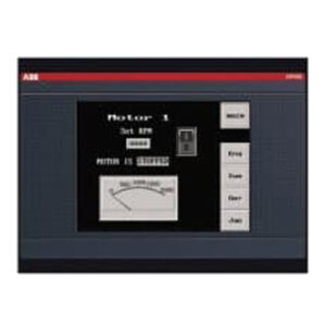
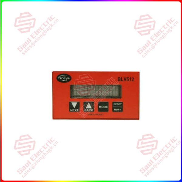
The BurnerLogix system offers optional vacuum fluorescent (VFD) and liquid crystal (LCD) displays that may be either plugged in or mounted remotely to give full language descriptors of current status and diagnostic lockout information. In order to change the factory default parameters stored in the programmer module an optional keypad/display (BLV512 or BLL510) is required. All configurable parameters are stored within the PROGRAM SETUP sub-menu. The keypad/display module provides tactile feedback keys that are used to access the sub-menus inherent in the BurnerLogix system.
The optional alpha-numeric display is made up of 2 lines by 16 characters per line and is available in either vacuum fluorescent or liquid crystal formats. The advantage of VFD is high brightness and extended temperature range to -40°F. Both displays contain a fully functional keypad allowing the user to easily scroll through the various menus to view the current operating status, review programmer configuration, and lockout history.
When mounted remotely using kits 129-178-4 or 129-178-8, each display meets NEMA 4X requirements. Refer to instruction sheet 133-675 for details.
BLL510
lf you need to inquire or purchase ,please send the product models to my email or call medirectly .
sunny He
[Email] sales@xiongbagk.cn
[Mobile] 86-18059884797
[WhatsApp] 86-18059884797
[Skype] sales@saulcontrol.com
BLL510 BurnerLogiX™ CONTROL SYSTEM FIREYE


 1 Year Warranty
