Description
Overview
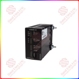
Essential details:DS200TCQCG1BGF GE RST Analog I/O Board
DS200TCQAG1BHF Technical Specifications
| Manufacturer | GE General Electric |
| Series | Mark V |
| Part Number | DS200TCQAG1BHF |
| Product Type | Analog I/O Board |
Product Description
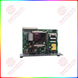
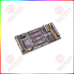
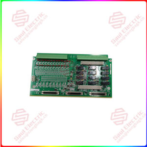
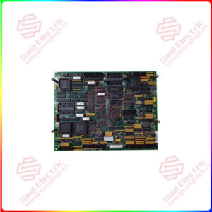
The GE RST Analog I/O Board DS200TCQAG1BHF contains four 34-pin connectors, two 40-pin connectors, and six jumpers. The board also has 6 LEDs. The GE RST Analog I/O Board DS200TCQAG1BHF is designed with 6 holes for installing the board in the board cabinet on the drive. The holes align with matching holes in the board rack and you can attach the board with washers and screws. When you remove the old board, keep the washers and screws together for use when you install the replacement board. Due to the high voltage in the board, it is critical to not let any metal parts fall into the board cabinet. If a screw or washer falls in the cabinet, locate the part and remove it from the drive. It the drive is started with the loose metal still inside, the metal might damage the drive or start a fire or cause a serious electrical shock.
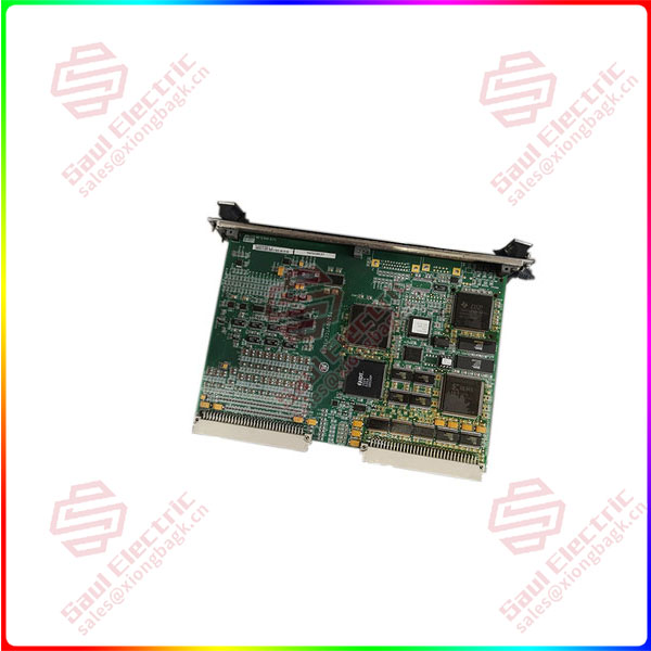
DS200TCQCG1BGF
lf you need to inquire or purchase ,please send the product models to my email or call medirectly .
sunny He
[Email] sales@xiongbagk.cn
[Mobile] 86-18059884797
[WhatsApp] 86-18059884797
[Skype] sales@saulcontrol.com
DS200TCQCG1BGF GE RST Analog I/O Board
Some guidelines are available to help prevent the metal screws and washers from dropping in the drive. When you remove the board, use one hand to hold the screwdriver and the other hand to guide the screwdriver to the screw and then to hold the screw when it is removed. To install a screw, use one hand to align the screw in the hole, and with the other hand, turn the screwdriver. Never over tighten the screws because the board might crack or break apart. Instead, only tighten the screw firmly in place. The washer helps protect the board from damage from over tightening.
Frequently Asked Questions about DS200TCQAG1BHF
Is there a manual describing DS200TCQAG1BHF?
Which connector is the data bus between DS200TCQAG1BHF and the STCA?
What does DS200TCQAG1BHF do?


 1 Year Warranty
