Description
Overview
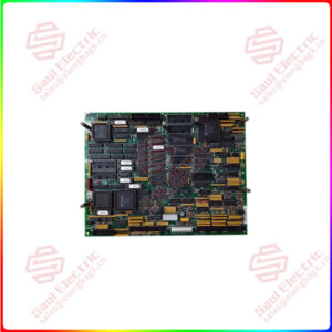
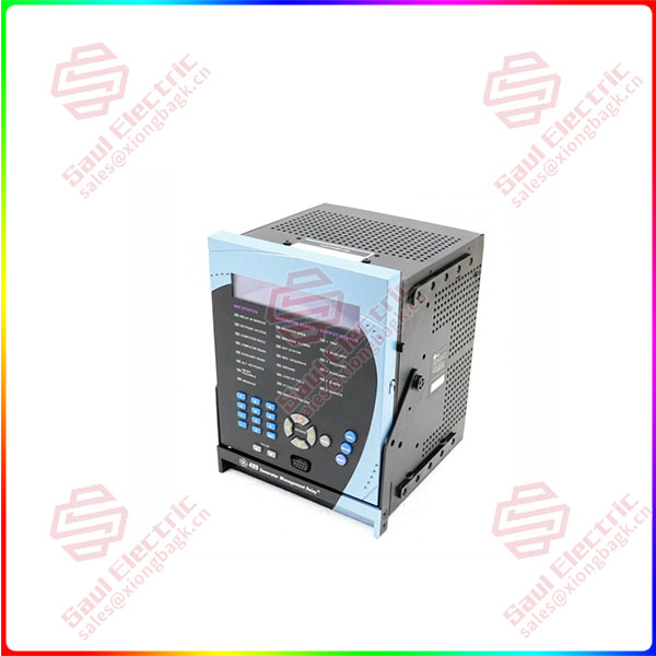
Essential details:469-P5-LO-A20-T GE 469 series Motor Management Relay
469-P5-LO-A20-T Technical Specifications
| Analog Current Inputs | 0 to 1 mA, 0 to 20mA, or 4 to 20mA |
| Shipping Weight | 17 lbs Max / 7.7 kg |
| nalog Current Conversion Range | 0 to 21 mA |
| Humidity | up to 90%, non-condensing |
| Shipping Dimensions | approx. 12” × 11” × 10” (W × H × D), or 30.5 cm × 27.9 cm × 25.4 cm |
| Operating Temperature | –40°C to +60°C |
| Case Mounting | Panel or 19-inch rack mount |
Product Description
Boasting the optional Ethernet connection of GE Multilin’s 469 series, the 469-P5-LO-A20-T is a Motor Management Relay which can use its Ethernet capabilities to run on the network rather than a mere RS242 or RS485 connection.
The twelve RTD inputs are each 3 wire: those wires are composed of 100 Ω Platinum (DIN.43760), 100 Ω Nickel, 120 Ω Nickel, 10 Ω Copper. The Resistance Temperature Detectors can monitor variables such as hottest temperature to determine when and where problems are cropping up within the system.
489-P5-HI-A20-T-H
lf you need to inquire or purchase ,please send the product models to my email or call medirectly .
sunny He
[Email] sales@saulcontrol.com
[Mobile] 86-18059884797
[WhatsApp] 86-18059884797
[Skype] sales@saulcontrol.com
469-P5-LO-A20-T GE 469 series Motor Management Relay
The 469-P5-LO-A20-T is capable of monitoring more than just temperature. It can also use its metering capabilities to record values pertaining to amperes, voltage, watts, frequency, and more. Data can be trended and exported from the EnerVista 469 program for analysis by users and technicians. The resulting conclusions from the data can be implemented through the relay’s setpoint system, creating more effective settings based on your system’s unique needs and operating environment.
This unit also features an enhanced faceplate with a wider LCD and more efficient placement of the keypad and LEDs. The display is 40-character, alphanumeric, and is easily viewed under a variety of lighting conditions. The display can also show different system values when not in active use, providing a quick and efficient reference point for users in the vicinity of the relay. The LED indicators also provide reference points, as they are able to turn green, amber, or red depending on the conditions of the system itself.
Frequently Asked Questions about 469-P5-LO-A20-T
What happens when the Relay has stopped or is running cool at times?
What should the settings be set at for an acceleration trip on the GE 469-P5-LO-A20-T Relay?
What if the motor is already hot and the relay has limited starting?


 1 Year Warranty
