Description
Overview
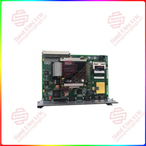
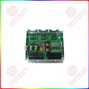
Essential details:DS200VPBLG2A GE VME Backplane Board
DS200VPBLG2A Technical Specifications
| Board Level | Base Level |
| Exciter Connector Type | 34-Pin Ribbon |
| Functional Acronym/Abbreviation | VPBL |
| Group Variation | G2 |
| Manufacturer | GE Industrial Systems, General Electric Company US |
| Number of VME Connectors | Eight |
| Part Specific Manual | GEI-100227 |
| Terminal Block | 12-Pin |
Frequently Asked Questions about DS200VPBLG2A
What are the power bugs that are within the DS200VPBLG2A board?

DS200VPBLG1A
lf you need to inquire or purchase ,please send the product models to my email or call medirectly .
sunny He
[Email] sales@xiongbagk.cn
[Mobile] 86-18059884797
[WhatsApp] 86-18059884797
[Skype] sales@saulcontrol.com
DS200VPBLG2A GE VME Backplane Board
What type of power connector does the DS200VPBLG2A board use?
How are the eight VME-type connectors in section J2 used on the DS200VPBLG2A board?
How is the Diagnostics Connector used?
Product Description
VME Backplane Board DS200VPBLG2A is part of the LS2100 Series produced by General Electric Industrial Systems. The model is the second version of the VPBL model. There are a number of sections within the VME Backplane, section J2 supports a number of boards within the LS2100 Series. The boards supported in section J2 are a DSPC, up to three Gate Distribution Status Boards, one exciter board, and an I/O extender daughterboard.
The DS200VPBLG2A model has many input/output definitions, the specific definitions in the J2 section of the mode are the eight VME-type connectors, of the eight six are positioned with double-wide spacing, the two that are left over are single-spaced and allow for the opportunity for more capability enhancements.
The DS200VPBLG2A model has a total of ten power bugs, the purpose of which is to electrically connect the P1 backplane to the VPBL. The model also has a thirty-four-pin ribbon connector, labeled as an EXJV. The purpose of the exciter connection is to handle all of the signals for the external exciter bridge.
If you have any questions regarding this model refer to the GEI-100227 VME Backplane Board VPBL User’s Guide. More information can be found on page twenty-one of the GEH-6373 Series Manual.


 1 Year Warranty
