Description
Overview
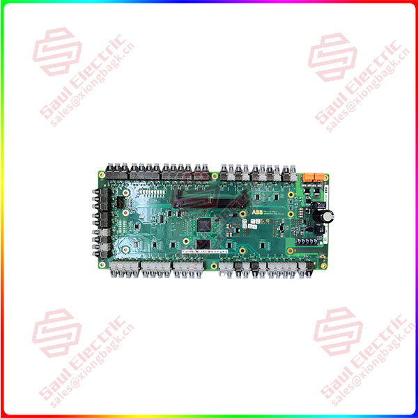
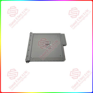
Essential details:IS420UCSBH4A Mark VIe Series UCSB Controller
lf you need to inquire or purchase ,please send the product models to my email or call medirectly .
sunny He
[Email] sales@xiongbagk.cn
[Mobile] 86-18059884797
[WhatsApp] 86-18059884797
[Skype] sales@saulcontrol.com
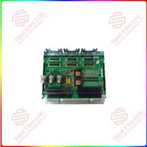
3BHE024855R0101 UFC921 MC INTERFACE BOARD ASSEMBLY
The UCSB Controllers offer the Following Advantages:
- Single module
- Built-in power supply
- No jumper settings required
- No battery
- No fan (UCSBSIA, UCSBHIA, UCSBH4A)
- Dual-redundant fans with IS420UCSBH3A
- Smaller panel footprint
- Flash memory can be conveniently updated
UCSB INSTALLATION:
A single module that installs directly to the sheet metal of the panel contains the controller. The dimensions for the module envelope and mounting are shown in the diagrams below. Every measurement is in inches. The UCSB must be attached to the panel as depicted, with the vertical airflow through the fins remaining unhindered.
UCSB SOFTWARE AND COMMUNICATION:
Software customized for the controller’s use is installed. Rungs or blocks can be run by it. Without needing to restart, small changes to the control software can be done online. The clocks of the 1/O packs and controllers are synchronized to within 100 microseconds using the IEEE 1588 protocol via the R, S, and T IONets. Through the R, S, and T IONets, external data is sent to and received from the control system database in the controller. This comprises the 1/0 modules’ process inputs and outputs.
Additionally, in a dual system, these are:
1. Data on initialization and internal state variables from the selected controller
2. Information on the synchronization and status of both controllers
This also covers the following in a triple modular redundant (TMR) system:
- Information on synchronization from all three controllers, internal state values for voting, and status
- Initialization data from the chosen controller
UCSB BOOT LED:
In the absence of a mistake, the boot LED remains on throughout the boot process. The LED will blink once per second (Hz) if an error is found. The LED blinks for 500 milliseconds, then goes off. The LED stays off for three seconds after the flashing phase. Flash count reveals failed condition.
The boot LED flashes continuously at a Hz rate if the flash image is genuine but the runtime firmware has not yet been loaded. The firmware loads and the boot LED goes off. Use the ToolboxST app to find out why the controller is blocked if it won’t connect online. After receiving an IP address, ToolboxSTplication configures itself over Ethernet.


 1 Year Warranty
