Description
Overview
Essential details:IS200TSVOH1BBB Servo Terminal Board developed
Part No.: IS200TSVOH1BBB
Manufacturer: General Electric
Country of Manufacture: United States of America (USA)
Span: 0.3532 to 4.054 V
Size: 17.8 cm high x 33.02 cm wide
Technology: Surface mount
Temperature Operating: -30 to 65oC
Product Type: Servo Terminal Board
Availability: In Stock
Series: Mark VI
Functional Description
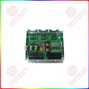
IS200TSVOH1BBB is a Servo Terminal Board developed by GE. It is a part of the Mark VI control system. The Servo Terminal Board (TSVO) interfaces with electro-hydraulic servo valves responsible for actuating steam/fuel valves in industrial systems. By providing both Simplex and TMR signals, TSVO ensures redundancy and fault tolerance, minimizing the risk of system failures and enhancing overall reliability. Redundant signal distribution and external trip integration contribute to system resilience and robustness.
Features
- Interface Components: Interfaces with two electro-hydraulic servo valves, which control the operation of steam/fuel valves in the system. Valve position is measured using linear variable differential transformers (LVDT), ensuring accurate feedback on valve positions.
- Communication Interfaces: Two cables connect TSVO to the I/O processor (VSVO), utilizing the J5 plug on the front of VSVO and the J3/4 connectors on the VME rack. These connections facilitate the transmission of control signals and feedback data between TSVO and the I/O processor.
- Signal Distribution: Provides Simplex signals through the JR1 connector, ensuring straightforward communication for essential functions.For redundancy and fault tolerance, TMR (Triple Modular Redundancy) signals are distributed to the JR1, JS1, and JT1 connectors, allowing for resilient operation even in case of component failures.
- External Trip Integration: Plugs JD1 or JD2 serve as connection points for an external trip from the protection module, enhancing system safety and reliability. Integration with the protection module enables swift response to critical events or abnormal conditions, allowing for timely shutdown or corrective actions.
- Compatibility and Expansion: Designed to seamlessly integrate with existing control systems and infrastructure, offering compatibility with standard connectors and communication protocols. The board layout and connectors facilitate easy expansion or integration of additional components or functionalities as per system requirements.
lf you need to inquire or purchase ,please send the product models to my email or call medirectly .
sunny He
[Email] sales@xiongbagk.cn
[Mobile] 86-18059884797
[WhatsApp] 86-18059884797
[Skype] sales@saulcontrol.com
IS200TSVOH1BBB Servo Terminal Board developed
Installation
- Mounting the Terminal Board: Secure the terminal board onto a suitable mounting surface using appropriate fixtures or brackets. Ensure the board is positioned securely and aligned correctly for easy access to terminal blocks and connectors.
- Wiring Sensors and Servo Valves: Sensors and servo valves are directly wired to two I/O terminal blocks mounted on the board. Each terminal block is secured in place with two screws and features 24 terminals capable of accepting wiring up to 12 AWG gauge.
Carefully connect the sensor and servo valve wires to their respective terminals on the terminal blocks, ensuring proper insulation and termination. - Shield Termination: Locate the shield termination strip attached to chassis ground, positioned immediately to the left of each terminal block. Connect the shield wires from sensors and servo valves to the shield termination strips, ensuring proper grounding for noise suppression and electromagnetic interference (EMI) protection.
- External Trip Wiring: Identify the designated connection points for external trip wiring, labeled as JD1 or JD2 on the terminal board. Plug in the external trip wiring to the appropriate connector based on system configuration and requirements.
- Cable Management: Organize and manage the wiring neatly to prevent tangling, interference, or accidental damage during operation. Use cable ties or clamps to secure the wires and maintain a tidy installation.
- Verification and Testing: Once all connections are made, carefully inspect the installation to ensure all wires are correctly terminated and secured. Conduct preliminary tests or checks to verify proper functionality and ensure that sensors, servo valves, and external trip connections are working as intended.
Fault Detection
- Servo Current Out of Limits or Non-Responsive:
- The TSVO board continuously monitors the current flowing through the servo valves.
- If the servo current exceeds predetermined limits or if the servo valves fail to respond to control signals, the board triggers a fault alarm.
- This fault detection mechanism promptly alerts operators to any issues with servo valve operation, allowing for timely troubleshooting and corrective action.
- Regulator Feedback Signal Out of Limits:
- The terminal board constantly monitors the feedback signals received from the regulators.
- If the feedback signals deviate from expected limits or exhibit abnormalities, indicating potential regulator malfunctions or inaccuracies, the board flags this as a fault condition.
- Detecting out-of-limit feedback signals helps ensure the accuracy and stability of the control system, enabling proactive maintenance to rectify regulator issues and maintain system performance.
- Failed ID Chip:
- Each terminal board component, including the ID chip, undergoes continuous monitoring.
- In the event of an ID chip failure or malfunction, where the chip fails to provide accurate identification information, the terminal board identifies this discrepancy.
- A failed ID chip can trigger a hardware incompatibility fault, indicating a potential issue with board identification or communication.
- By detecting failed ID chips, the terminal board ensures the integrity of component identification and facilitates system diagnostics and troubleshooting.


 1 Year Warranty

