Sale!

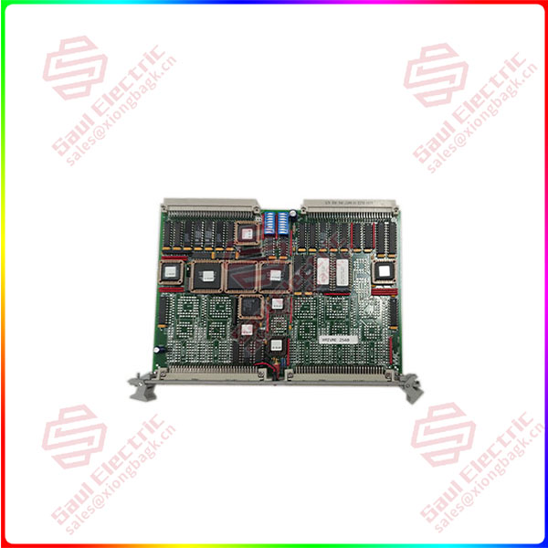
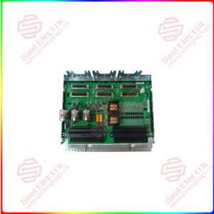
VMIVME-2540-000   24-Channel Intelligent Counter/Controller  

VMIVME-2540 ICC performs these functions automatically. The on-board CPU maintains data structures in shared local memory for buffering measurements and queueing control commands. Measurement functions are also supported by a Continuous Measurement Mode in which measurements are made repeatedly without host CPU involvement. I/O connections are routed through high-density connectors located on the front panel with support for differential and single-ended signal levels. The user data exchange interface for measurement and generation modes complies with ANSI/IEEE Standard
754-1985 for 32-bit floating-point arithmetic. Integer modes operate with two’s complement signed arithmetic and with unsigned arithmetic.
Categories: ,

Description

Overview


Essential details:VMIVME-2540-000   24-Channel Intelligent Counter/Controller  

VMIVME-2540 ICC performs these functions automatically. The on-board CPU maintains data structures in shared local memory for buffering measurements and queueing control commands. Measurement functions are also supported by a Continuous Measurement Mode in which measurements are made repeatedly without host CPU involvement. I/O connections are routed through high-density connectors located on the front panel with support for differential and single-ended signal levels. The user data exchange interface for measurement and generation modes complies with ANSI/IEEE Standard
754-1985 for 32-bit floating-point arithmetic. Integer modes operate with two’s complement signed arithmetic and with unsigned arithmetic.
TECHNICAL DESCRIPTION — The VMIVME-2540 ICC is comprised of three sections: the VMEbus slave DTB interface which arbitrates for the local CPU resources, the CPU with firmware and support logic, and the circuitry which implements the measurement and control functions. The block diagram of the VMIVME-2540 ICC is shown in Figure 1.

The ICC counter circuitry consists of six programmable System Timing Controllers (STCs). Each STC provides the ICC with four high-speed counter/waveform synthesis interfaces, giving the VMIVME-2540 twenty-four channels of digital measurement and control. The STC counters may be configured individually or in groups of up to four to implement the various measurement and control functions.
The on-board 68HC000 CPU configures and manages each STC interface directly, allowing the VMEbus host interface to be elevated above the hardware level. Ordering options allow the VMIVME-2540 to be factory configured with 1, 2, 4, or 6 System Timing Controllers. The inputs and outputs of the System Timing Controllers are buffered at the front panel connectors with RS-422 line receivers and line drivers. TTL input signal compatibility is supported by connecting the inverting input of the RS-422 line receiver to an on-board 1.4 V reference through the front panel, and the TTL signal to the noninverting input.
The user interface of the Intelligent Counter/Controller is implemented by a 15 MHz 68HC000 CPU supported by 64 Kbyte of EPROM firmware, 128 Kbyte of zero-wait-state static RAM, and highly-integrated control and interrupt logic. The VMEbus host programs the ICC by queueing function control blocks in local memory and  issuing commands. The CPU responds to the commands by interpreting the function control blocks, configuring the system timing controllers, and then acknowledging the host command. Once configured, the CPU maintains data structures of measurement data in local memory and interrupts the VMEbus host when a measurement or control process is complete.

VMIVME-2540

lf you need to inquire or purchase ,please send the product models to my email or call medirectly .

sunny  He

[Email] sales@xiongbagk.cn

[Mobile] 86-18059884797

[WhatsApp] 86-18059884797

[Skype] sales@saulcontrol.com

VMIVME-2540-000   24-Channel Intelligent Counter/Controller

The slave VMEbus interface of the VMIVME-2540 locates the 64 Kbyte VMEbus local memory window in A32 or A24 address space with DIP switches, with nonprivileged and/or Supervisory access. The VMEbus host must arbitrate with the 68HC000 CPU for local bus access since the RAM is shared. The data accesses may be D32, D24, D16, and D08, and unaligned transfers are supported. Because the local CPU executes its code from RAM, the arbiter relinquishes control of the local resources after a single VMEbus data transfer.
The Intelligent Counter/Controller supports two VMEbus interrupter modules which may assert any of two IRQ levels simultaneously. When serviced, the interrupter modules respond with an 8-bit interrupt vector and automatically clear the pending IRQ. The CPU maintains a queue of pending interrupt events in memory, writing a new IRQ to the interrupter modules when the previous event is cleared.
The RS-422 differential signals should be connected by twisted pair insulated wires, 24 AWG solid or stranded-copper conductors (R < 30 Ω/ 1,000 ft for other conductors), with a maximum cable length of 4,000 feet. Care should be taken to ensure that each signal group is properly grounded for reliable operation.
TTL signals may be connected by flat 96-conductor ribbon cable, 30 AWG insulated copper-stranded conductor.
The corresponding female 96-pin DIN connector for flat-ribbon cable is ERNI 913.031 or similar. It is recommended that the total cable length be 50 feet or less for the TTL application with attention given to maximum signal transition rate and signal degradation over distance. RS-422 differential interface is clearly superior for longer cable lengths.
If the user wishes the I/O signals from the VMIVME-2540 front panel to be broken out at terminal blocks, the VMIACC-BT04 Dual 96-pin Transition Panel is suggested. The VMIACC-BT04 is a 19-inch rack-mountable panel which breaks all 192 signals out from two DIN 96-pin connectors to standard terminal blocks. Connection between the VMIACC-BT04 and the VMIVME-2540 front panel is made by 96-conductor ribbon cables, three foot length recommended.