Sale!

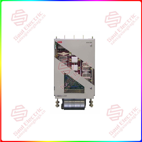
DCF506-0140-51 DCS Thyristor Power Converters for DC drive systems

General remarksThe term “DCS thyristor power converter” is a general designation for basic DC converters from ABB. This termcan be found in many parts of the relevant documentation. The precise product name in accordance with thebrief descriptions given below characterizes a specific unit.
Brief description of DCS 500BThe DCS 500B unit range is an enhancement developed from the DCS 500 range.The DCS 500B is an armature converter with the following standard features:*Design and commissioning tools * Monitoring functions * Communication via databus * Human-machineinterface * More than 300 additional functions blocks programmable under Win-dows * Graphical Application Desiner * Plain text display * FOR HIGH POWER

Categories: ,

Description

Overview


Essential details:DCF506-0140-51 DCS Thyristor Power Converters for DC drive systems

General remarksThe term “DCS thyristor power converter” is a general designation for basic DC converters from ABB. This termcan be found in many parts of the relevant documentation. The precise product name in accordance with thebrief descriptions given below characterizes a specific unit.
Brief description of DCS 500BThe DCS 500B unit range is an enhancement developed from the DCS 500 range.The DCS 500B is an armature converter with the following standard features:*Design and commissioning tools * Monitoring functions * Communication via databus * Human-machineinterface * More than 300 additional functions blocks programmable under Win-dows * Graphical Application Desiner * Plain text display * FOR HIGH POWER
Brief description of DCF 500BWith software release 21.232 or higher DcS 500B has a ‘3-phase field exciter mode’. A DCF 500B is a three.phase field exciter based on the programmable DCS 500B software and the SDCS-CON-2 control board.The interface board PlN-1x is modified: . an overvoltage protection unit DCF 505/506 is reguired.
Brief description of DcS 600The DCS 600 converter family is based on the hardware developed for the DCS 500B type.Instead of a COM-x board, the SDCS AMC DC board is used. PC tools will be connected there. as well asthe APC (Application controller), if the APC is used as a PLc. lf a different PLC is used, separate adaptermodules are needed. They must be connected to the AMC-DC board, too. The software code always beginswith S15.xxx for MultiDrive or S18.xxx for Crane drives.
Brief description of DCF 600The DCF 600 unit range is intended to be used for supplying motor fields and is based on the hardware andsystem configuration of the DCS 600 unit. The software is identical to the DCS 600 software. Similar to DCF500B units the DCF 505/506 overvoltage protection unit is required. The same modification is applied to thePlN-1x board, compared to DCF 500B.
Brief description of Dcs 400The DCS 400 is the smallest drive in its class. The compact design has been partly achieved by a fully integratedfield exciter based on lGBT technology. A commissioning wizard – available on the control panel and the PCtool . makes startup of the drive easy. in addition, the DCS 400 contains application macros.

DCF506-0140-51

lf you need to inquire or purchase ,please send the product models to my email or call medirectly .

sunny  He

[Email] sales@xiongbagk.cn

[Mobile] 86-18059884797

[WhatsApp] 86-18059884797

[Skype] sales@saulcontrol.com

DCF506-0140-51 DCS Thyristor Power Converters for DC drive systems

a.The power sections of sizes Ci and C2 aremonitored by an electrically isolated PTC ther-mistor detector, which is installed on the likewiseelectrically isolated heat sink near the thyristors.The resistance change proportional to thetemperature is acquired and evaluated in theunit’s software. lf the temperature rises above acertain value predefined by the unit codinginvolved, then first an alarm will be outputted.and if the temperature continues to rise -anerror message. This means that changes in therated cooling conditions, such as cooling airvolume and temperature, the fan itself, overloaddue to an excessively high load current, etc. aredetected.
b.The size-A5 power section is likewise monitoredby an electrically isolated PTC thermistor detector, which is installed on the non-isolated heatsink in an isolated configuration. Evaluation ofthe resistance and the protection effect corre-spond to those mentioned for point (a.) above.
c. The size A6 and A7 power section is not directlymonitored by an electrically isolated PTC ther-mistor detector. For this size, the same thermis-tor detector is used as for (a.) and (b.) above, but it is here not mounted on a heat sink but close tothe fan air outlet. The detector thus measures thepower section’s radiated heat and any changesin the cooling air temperature and volume. Sincethe cooling air volume can only be detectedindirectly, a differential-pressure switch has beenadditionally fitted at the unit’s housing, alwayslocated close to the power terminals.The resistance change proportional to thetemperature is acquired and evaluated in theunit’s software. lf the temperature rises above theparameterized value, then first an alam will beoutputted, and -if the temperature continues torise -an error message. The value to be set forthis parameter must not be more than 10 de-grees above the permissible ambient tempera-ture.
The differential-pressure switch compares thepressure inside the unit with the nomal atmos-pheric pressure. lf the fan has been switched onand the unit door closed (and no unit casingshave been removed), the pressure switch willsignal “Cooling conditions ok”, which means thedrive may be enabled. There is no need to setany specific differential pressure (recommenda-tion: centre setting).