Sale!

IS200DSFCG1A DRIVER SHUNT FEEDBACK BOARD

Part No.: IS200DSFCG1A
Manufacturer: General Electric
Function: Driver Shunt Feedback Board
LED: 5
Series: Mark VI
Size: 2 inches height, 3 inches length
Manual: GEI-100263
Product Type: PCB
Availability: In Stock
Country of Manufacture: United States (USA)

Categories: ,

Description

Overview


Essential details:IS200DSFCG1A DRIVER SHUNT FEEDBACK BOARD

SPECIFICATIONS

Part No.: IS200DSFCG1A
Manufacturer: General Electric
Function: Driver Shunt Feedback Board
LED: 5
Series: Mark VI
Size: 2 inches height, 3 inches length
Manual: GEI-100263
Product Type: PCB
Availability: In Stock
Country of Manufacture: United States (USA)

Functional Description

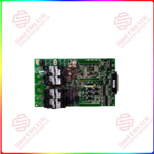
IS200DSFCG1A is a Driver Shunt Feedback Board designed and developed by GE. It belongs to General Electric’s Speedtronic Mark VI series. The Driver Shunt Feedback Board have features such as MOV protection, jumper pins for customization, current sensing and fault detection circuits, galvanic and optical isolation, compatibility with Innovation SeriesTM source bridges and AC drives, and precise mounting and orientation requirements. These features collectively contribute to the board’s reliability, functionality, and effectiveness in drive/source applications, providing essential control and feedback capabilities for power conversion systems.

Product Attributes

  • Metal Oxide Varistor (MOV): Located near the upper left corner of the PCB, the board incorporates a circular red Metal Oxide Varistor (MOV). This component helps protect the board and the connected circuitry from transient voltage spikes or surges by diverting excessive electrical energy to ground.
  • Jumper Pins: Features six jumper pins arranged in three pairs near the upper center. Each pair of jumper pins is labeled with designators such as PL, PL1, and PL2. These jumper pins provide the ability to configure and customize certain settings or connections on the board, allowing for flexibility and adaptability in system integration.
  • Current Sensing and Fault Detection Circuits: Includes a current sensing circuit that enables the accurate measurement and monitoring of current levels in the system. This feature is essential for precise control and protection against overcurrent conditions. Additionally, a fault detection circuit is incorporated to detect and identify any faults or abnormalities in the system, ensuring timely and effective fault management.
  • Galvanic and Optical Isolation: Both the feedback and driver circuits on the Gate Driver/Shunt Feedback Board are designed with galvanic and optical isolation. This isolation helps prevent electrical noise and interference, enhancing the stability and accuracy of the feedback signals and driver outputs. It also improves safety by isolating different electrical potentials, reducing the risk of electrical faults and ensuring reliable operation.
  • Compatibility with Innovation SeriesTM Source Bridges and AC Drives: Specifically designed to be used with the Innovation SeriesTM 1000 Amp and 1800 Amp Pulse Width Modulated (PWM) source bridges and AC drives. These source bridges and AC drives are critical components in power conversion applications. The board serves as an interface between the drive bridge personality interface board and the drive control system, enabling seamless integration and communication.
  • Mounting and Orientation: To ensure proper installation, the board must be mounted directly to the upper and lower IGBT modules in each phase leg. The gate, emitter, and collector connections to the IGBT hold the board securely in place. Correct orientation is crucial for aligning the mounting holes with the corresponding gate, emitter, and collector connections, ensuring proper electrical and mechanical integration.

IS200DSFCG1A

lf you need to inquire or purchase ,please send the product models to my email or call medirectly .


Zona

[Email] sales@saulcontrol.com

[Mobile] 86-18150899970

[WhatsApp] 86-18059884797

IS200DSFCG1A DRIVER SHUNT FEEDBACK BOARD

Features

  • Shunt Feedback: Built-in shunt resistor that provides feedback on the current flowing through the system. This feedback is used to regulate the current and prevent overloading or other issues that can occur when the current is not properly controlled.
  • Amplification: The board has a built-in amplifier that amplifies the input signal to a level that can be easily processed by the control system.
  • Isolation: Provides electrical isolation between the input signal and the output signal, which helps protect the control system from any electrical noise or surges in the input signal.
  • Signal Output: Provides a high-level output signal that can be used to control a motor or valve, or interface with a PLC or DCS system.
  • Protection: The board provides protection features such as overvoltage protection and short-circuit protection to safeguard the connected equipment.
  • Modularity: The board is modular, meaning that it can be easily replaced if it fails or needs to be upgraded.

Excitation Control System

  • The excitation control system provides dc power to the synchronous generator’s field.
  • The exciter uses the field current to control the generator’s ac terminal voltage and/or reactive volt-amperes. The exciter is delivered in freestanding floor-mounted indoor NEMA 1 metal cabinets. The cabinet lineup is made up of several cabinets that are bolted together. The cable can enter from the top or bottom.

Power Supplies

  • An isolation transformer powers the high voltage side of each of the driver/monitor circuits.
  • This transformer’s primary is connected to a 17.7 volt peak (35.4 volt peak to peak), 25 kHz square wave.
  • The third secondary is fullwave rectified and filtered to provide the isolated t12 V needed by the shunt current feedback VCO and fault detection circuitry (unregulated, +10%, 100 mA maximum average for each voltage).
  • A light 5 V logic supply is also required by the shunt circuit, which is generated by a 5V linear regulator connected to the +12 V supply (+10%, 100 mA average maximum). The only regulated component is the 5V power supply.

Trip System

  • On turbines without mechanical overspeed bolts, the control can send a trip command from the main processor card to the VTUR card in the Control Module(s) or from the Backup Protection Module. The negative side of the 24Vdc/125Vdc circuit is wired to the TRPG, which is driven by the card in the Control Module, and the positive side is wired to the TREG, which is driven by the VPRO in each section of the Backup Protection Module.
  • A typical system trip initiated in the Control Module(s) will close the servo valve actuators, stopping fuel or steam flow and de-energizing (or energizing) the hydraulic trip solenoids from the VTUR and TRPG. If cross tripping is used or an overspeed condition is detected, the VTUR/TRPG will trip one of the solenoids while the VPTRO/TREG will trip the other (s).

Storage Precautions

Cover the equipment with the following requirements:

  • Keep the equipment clean and dry, protected from precipitation and flooding.
  • Use only canvas type covering material
  • no plastic.

Unpack and label the equipment as described.

  • Maintain the following environment in the storage enclosure: -40 to 80 degrees Celsius recommended ambient storage temperature limits.
  • Free of dust and corrosive elements such as salt spray or chemical and electrically conductive contaminants in the surrounding air
  • A relative humidity range of 5 to 95%, with provisions for condensation prevention.
  • No rodents
  • No temperature fluctuations resulting in moisture condensation