Description
Overview
Essential details:IS200TRLYHIBFD Relay Terminal Board
Product Description
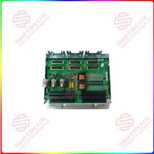
The IS200TRLYH1B is a termination relay card for the Mark VI turbine control system manufactured by GE. This board is the “B” revision of the TRLY terminal relay board and features the following characteristics:
- Voted Coil Drive Feedback
- Socketed Sealed Mechanical Relay
- MOV Suppression
- 48 Barrier Terminals
Physical Description of the IS200TRLYH1B:
The IS200TRLYH1B contains two (2) large black terminal block on its left edge. Each terminal block features twenty-four (24) metal terminals which are silver. This adds up to a total of forty-eight (48) terminals. Every terminal has been labeled on the terminal blocks in white print. Four (4) connector ports have been placed on the right border of the IS200TRLYH1B. Three (3) of the connector ports are aligned vertically on the edge and the last is sitting parallel to the connector port at the bottom. Near the center of the IS200TRLYH1B there is a long line of relays which are white and black with transparent covers shaped like cubes. These components have been attached to the PCB with black wires. On both sides of each relay is a black transistor which is circular. Paired together with every transistor is a round red MOV or metal oxide varistor. Five (5) of these relays are lined up vertically on the top half of the IS200TRLYH1B. Five (5) additional relays have been aligned on the PCB’s lower half.
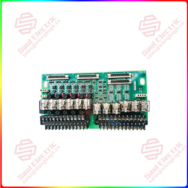
IS200TRLYH1B
Product parameter
| Feedback | Voted Coil Drive |
| Manufacturer | GE Energy |
| Power Distribution | 6 Fused Branches, 1 Special Unfused |
| Relays | 12 Form C Relays, 24 DC 3A, 125 DC .6A, 120/240 AC 3A |
| Part Number | IS200TRLYH1B |
| Product Type | Relay Terminal Board |
| Instruction Manual | GEH-6421Q |
APPLICATION
The IS200TRLYH1B is a Relay Output Terminal Board developed by GE under the Mark VIe series. There are 12 plug-in magnetic relays on the Relay Output with Coil Sensing (TRLY1B) terminal board. The first six relay circuits can be set up with jumpers to drive external solenoids or dry, Form-C contact outputs. For field solenoid power, a basic 125 V dc or 115/230 V ac source or an optional 24 V dc source with personal jumper-selectable fuses and onboard suppression can be offered. The next five relays (7–11) are isolated Form-C contacts that are not powered. An isolated Form-C contact is used on output 12 for specialized uses like ignition transformers.
IS200TRLYH1B Compatibility
Simplex and TMR applications are supported by the PDOA/YDOA I/O pack when using the TRLY 1B. The terminal board’s DC-37 pin connections accept the I/O pack as a plug-in. For simplex systems, connector JA1 is used, while for TMR systems, connectors JR1, JS1, and JT1 are used.
IS200TRLYH1B Installation
Wire the two I/O terminal blocks on the terminal board, TRLY1B Terminal Board Wiring, directly with the wires for the 12 relay outputs. Each block has 24 terminals that may accommodate wires up to #12 AWG and is secured with two screws. Each terminal block has a shield terminal strip on the left side that is connected to chassis ground. The solenoid power for outputs 1-6 should be connected to JF1. Power can be daisy-chained to additional TRLYs using JF2. Alternatively, when JF1/JF2 are not in use, power can be connected directly to TB3.
Connect output 12 of the special solenoid to connector JG1 to provide electricity. The factory removes jumpers JP1-JP6 and ships them in a plastic bag. If a field solenoid needs electricity, reinstall the proper jumper. Check each loop’s energization individually in accordance with best practices, and install the jumpers as necessary. Remove the fuses from isolated contact applications to make sure that the power bus is free of suppression leakage.
IS200TRLYH1B Operation
Dry Contacts
If these terminal boards are utilized as dry contacts to switch ac voltage utilizing circuits 01 through 06 while also receiving 125 V dc power through JF1, JF2, or TB3, ac power will be present on the “NO” relay terminal until all fuses and jumpers for a circuit are removed. Additionally, the contact will bind the ac voltage to N 125 V dc when it shuts.
Similar circumstances apply to the P-125. The sum of the ac peak voltage and the 125 V dc is applied to MOVs linked between the dc and ground because the neutral of the majority of ac supply is grounded. The MOV rating is adequate to tolerate 120 V ac in those situations. The peak voltage will, however, exceed the MOV rating in 240 V ac applications, leading to failure. It is best to avoid using these circuits for ac switching because of this.
Simplex
On the TRLY 1B are mounted jumpers, fuses, and relay drivers. D-type connectors monitor feedback voltages and transmit control signals between the I/O processors and TRLY1B through JA1 for simplex operation. Relays have a 3.0 A rating and are driven at the frame rate. 500 V ac is the maximum allowable contact-to-contact voltage for one minute. For one minute, the coil to contact voltage is rated at 1,500 V ac. 10 ms is the normal operating time.
TMR
Relay control signals are fanned into TRLY1B for TMR applications from the three I/O processors R, S, and T through connectors JR1, JS1, and JT1. These signals are put to a vote, and the outcome determines which relay driver gets the signal. All three I/O processors provide shared diode power to the relay coils.
IS200TRLYH1B Specifications
Number of relay channels on one TRLY1B board
- 12
- 6 relays, with optional solenoid driver voltages
- 5 relays, with dry contacts only
- 1 relay, with 7 Ampere rating
The rated voltage on relays
- Nominal 125 V dc or 24 V dc
- Nominal 115/230 V ac
Max load current
- 0.6 Ampere for 125 V dc operation
- 3.0 Ampere for 24 V dc operation
- 3.0 Ampere for 115/230 V ac, 50/60 Hz operation
Max response time on
25 ms typical
Max response time off
25 ms typical
Diagnostics
The following diagnostic procedures are performed on the terminal boards’ components:
- At the frame rate, each relay’s output (coil current) is monitored and compared to the command. An alarm is latched if there is no agreement after two inspections in a row.
- An alarm is latched if the solenoid excitation voltage drops below 12 V dc, which is monitored downstream of the fuses.
- A composite diagnostics alert, L3DIAG xxxx, is triggered if any one of the outputs becomes unhealthy.
- A hardware incompatibility fault is produced when an ID chip is read by the I/O processor and a mismatch is discovered.
- Monitoring of relay contact voltage.
- The configuration application has information about each diagnostic’s specifics. The diagnostic signals can be individually latched and, if they become healthy, reset with the RESET DIA signal.
lf you need to inquire or purchase ,please send the product models to my email or call medirectly .
Same day shipment of 1000 parts
My company under the Sales and Marketing Department, technical engineering Department, after-sales service department, the department of comprehensive management. We can help your business with good service.
1. Sales Department 24/7 service. Handles your requests for any PLC DCS products in a timely manner with patience and professionalism.
2. The engineering department ensures that the products have no quality problems. All products will be inspected before shipping.
3. The financial department checks the payment and refund in time.
4. The warehouse department will carefully check the list of goods, carefully pack them, and deliver the goods in time.
5. After-sales Service Department has a full-time after-sales service team, subordinate to the sales department, and users can timely respond to service requests.

Shipping
Superiority products IS200TRLYHIBFD Relay Terminal Board
| PFCL201CE ABB Pressure sensor controller | KJ2231X1-EA1 4-20 mA Series 2 Card EMERSON |
| MTL BPHM64 Eaton Safety grid base plate | 330106-0530-10-02-05 Proximity Probes Bently Nevada |
| 1794-IF4IXT Allen Bradley Flex I/O 1794 series input module | Max-4/11/03/032/99/1/1/00 SERVO MOTOR ELAU |
| 1734-IM4 Allen Bradley POINT I/O 4 Point Digital Input Module | 330104-00-08-90-02-05 Proximity Probes Bently Nevada |
| 1769-ECR Allen-Bradley Right end cover (ECR) module used together | D201139L Metso RT node PC AP31 D200137 personality module |
| 136188-02 Bently Nevada Ethernet /RS232 Modbus I/O module | D201376 Metso RT node PC AP31 D200137 personality module |
| AI02J ABB Analog input module | IS220PRTDH1A 336A4940CSP6 Resistance Temperature Device (RTD) Input Module GE |
| DSSA165 ABB Ac power module | IS220PSCAH1A 336A4940CSP9 Mark VI component GE |
| PXIe-1073 NI PXI Chassis | IS220PDIAH1BE 336A5026ADP4 Resistance Temperature Device (RTD) Input Module GE |
| F860-CA HONEYWELL Series C “fieldbus interface module | IS420ESWBH3AX GE Analog I/O modules |
| DSSA165 ABB Ac power module | 516TX 336A4940DNP516TX GE 516TX-A Industrial Ethernet Switch |
| 125840-02 Bently Power module | 128277-01 Future Expansion Faceplate Bently Nevada |
| 125680-01 BENTLY Displacement detection module | A413139 PC BOARD CIRCUIT BOARD MODULE ASSEMBLY METSO |
| 147663-01 BENTLY Communication analog output module | D201471 Metso RT node PC AP31 D200137 personality module |
| 125800-01 Bently Nevada Key phase input/output module | A413188 PC BOARD CIRCUIT BOARD MODULE ASSEMBLY METSO |
| 140471-01 Bently Nevada Developed I/O module with internal terminal | A413331 PC BOARD CIRCUIT BOARD MODULE ASSEMBLY METSO |
| 3500/22M 138607-01 Bently Detector module | D201466 Metso RT node PC AP31 D200137 personality module |
| 3500/94 145988-01 BENTLY Display module | 85UVF1A-1QD Fireye Integrated Flame Scanner with Internal Flame Relay |
| 3500/42M 176449-02 bently nevada Shaft vibration module | 516TX 336A4940DNP516TX GE A microprocessor device |
| 3500/92 136180-01 bently nevada Communication gateway module | 516TX-336A4940DNP516TX GE microcontroller |
| 136180-01 Bently Nevada Communication gateway module | 2MLR-CPUHT HONEYWELL CPU HT bus function |
| 3500/92-03-01-00 Bently Nevada 3500/92-03-01-00 | 177313-01-01 BENTLY NEVATA Vibration monitoring module |
| 7264 ABB The four-channel SSI interface module features automatic | PXIE-6556 NI Automatic industrial control module |
| MDB-8E SARTORIUS Load cell | PFCL201CE ABB Pressure sensor controller |
| 3500/15 127610-01 Bently Nevada Digital input module | MTL BPHM64 Eaton Safety grid base plate |


 1 Year Warranty
