Description
Overview
Essential details:05701-A-0302 SINGLE CHANNEL CONTROL CARDS
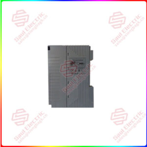
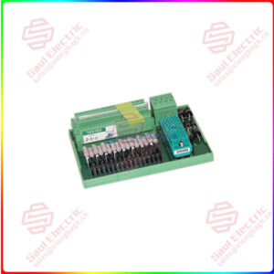
The 5701 Single Channel Control Card provides control, display and alarm facilities for a connected gas detector. The front panel display indicates the gas reading and channel status while LEDs are used for alarms. A push-button is provided for resetting the alarms and selecting the card for use with the Engineering Card.
The operation of the control card is microprocessor controlled and is fully definable for a wide range of connected gas detectors and application requirements. The software configuration setup is stored in an EEPROM.
There are two types of control card depending on the type of gas detector being fitted to the system:
a. Single Channel Control Card 4 – 20mA. Part Number 05701-A-0301.
b. Single Channel Control Card Catalytic. Part Number 05701-A-0302.
Each of the above control cards consist of a single channel control card fitted with the respective plug-in sensor drive module.
An optional Analogue Output Module can also be plugged into the single channel control card to provide a remote output of the channel card readings.
The sensor cable screen or steel wire armour (or braid), as appropriate, should be connected to the system (protective) earth. This can be achieved where the cable enters the cabinet by using a metal cable gland, or by other suitable means, and avoiding any screen ‘tails’ within the cabinet.
Where the cable consists of a separate screen sheath and wire armour (or braid), the armour should be connected, at the cabinet entry, to the protective earth and the screen sheath should be connected to the GROUND terminal of the Field Interface/Relay Card or to a suitable instrument earth point.
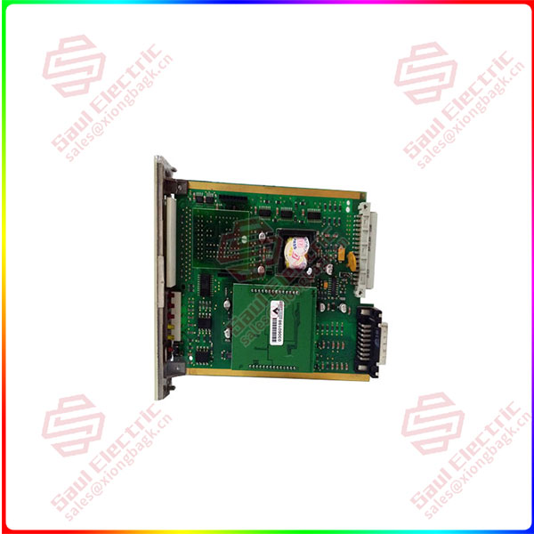
05701-A-0302
lf you need to inquire or purchase ,please send the product models to my email or call medirectly .
sunny He
[Email] sales@xiongbagk.cn
[Mobile] 86-18059884797
[WhatsApp] 86-18059884797
[Skype] sales@saulcontrol.com
05701-A-0302 SINGLE CHANNEL CONTROL CARDS
The alarm relays may be configured for either normally de-energised or normally energised operation. Check the configuration sheet supplied with the system to determine the operating mode of the relays on each channel. The energisation mode of the relays can be reconfigured easily using a computer attached to the Engineering Port. Contact Zellweger Analytics or your local agent for more information.
The analogue output can be configured for 0 – 20mA or 4 – 20mA output modes. Check the configuration sheet supplied with the system to determine the factory configured operating mode. The operating mode can be reconfigured easily using a computer attached to the Engineering Port. Contact Zellweger Analytics or your local agent for more information.
The analogue output can be connected to voltage input device (eg. chart recorders) by including an external sense resistor in series with the loop and connecting the device input in parallel with the resistor. ie. Use a 100 ohm resistor and select an input range of 2V on the chart recorder.


 1 Year Warranty
