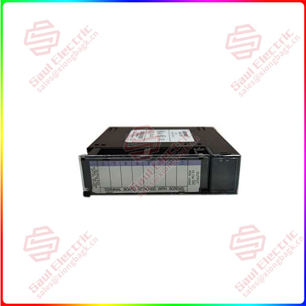
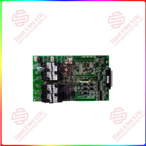
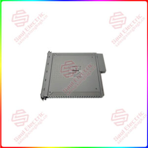
On the top of the module, there is an LED block with two horizontal rows of green LEDs. One row is labelled A1 while the other is labelled B1. The first row is for points 1 through 8 and the second row is for points 9 through 16. These LEDs indicate the ON/OFF status of each point on the module. There is also a red LED, which is labelled “F”. This is located between the two rows of green LEDs. Whenever any fuse is blown, this red LED turns on. This module has two 5-amp fuses. The first fuse protects outputs A1 to A4 while the second fuse protects outputs A5 to A8. Both of these fuses are connected to the same common by electrical means.
The IC693MDL730 has an insert to go between the surfaces of the hinged door. This door should be closed during operation. The surface facing the inside of the module has info on circuit wiring. On the outer surface, circuit identification information may be recorded. This unit is a low-voltage module, as denoted by the blue color-coding on the outer left edge of the insert. To operate it with the Series 90-30 PLC system, users can install the module in any I/O slot of either a 5 or 10-slot baseplate.


 1 Year Warranty
