Description
Overview
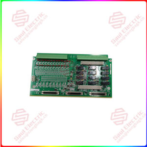
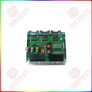
Essential details:IS200EGPAG1B PAMC Acoustic Monitor (Processor)
lf you need to inquire or purchase ,please send the product models to my email or call medirectly .
sunny He
[Email] sales@xiongbagk.cn
[Mobile] 86-18059884797
[WhatsApp] 86-18059884797
[Skype] sales@saulcontrol.com
IS200EGPAG1B PAMC Acoustic Monitor (Processor)
Conduction Current Sensors
- All three phases of the bridge input are equipped with conduction current sensors.
- The EGPA serves as an interface between these sensors, which are Hall Effect sensors located on the EXCS (Excitation Control System) boards, and the main control system.
- Power is supplied to the EXCS, and the EGPA receives signals from the EXCS indicating the status of current flow through each leg of the three-phase bridge input.
- These status signals are delivered to the EGPA through connectors J9 and J10. The EGPA conditions these signals and transmits the bridge’s current status to the controller.
Bridge Temperature Sensors
- The temperature of the bridge is monitored using an RTD (Resistance Temperature Detector) sensor input or a temperature switch input.
- In new exciters, only the RTD input is used, and jumpers on the EGPA disable the temperature switch inputs.
- In cases where a bridge is being retrofitted with an EX2100 control, the two temperature switch inputs are utilized to interface with temperature switches already mounted on the bridge. In this scenario, the RTD input is left open to disable it.
- Both the RTD and temperature switch inputs are connected to the EGPA at connector J13.
Airflow Sensors (Fan Rotation)
- To prevent overheating, airflow sensors are used to detect the loss of fan cooling in the bridge.
- It can accommodate up to four fans, which are connected to it through connector J12.
- The EGPA accepts either a pulsed or dry-contact, normally open sensor input from the fans. The mode of signal detection is configured through berg jumpers JP2-JP4.
Line Filter Fuse Failure Sensor
- A line filter fuse failure is sensed and monitored through connector J14 on the EGPA.
- This sensor input accepts a single, normally closed, dry contact input. It is designed to detect any failure in the line filter fuse, providing an early indication of potential issues with the power supply.
Replacement Procedures
- De-Energize the Exciter: Ensure the exciter where the board is housed has been powered down to avoid any electrical hazards during the replacement process.
- Electrical Circuit Test: Open the Power Conversion Cabinet door and perform thorough tests on electrical circuits to verify that power has been completely shut off before initiating any handling.
- Check LEDs: Confirm that all LEDs are turned off to ensure no residual power or signal transmission through the board.
- Label Verification for Cables: Ensure that each cable connected to the board is appropriately labeled with the correct connector name as indicated on the board. Proper labeling simplifies the reconnection process later on.
- Carefully Disconnect Cables: With caution, disconnect all cables attached to the board, paying attention to avoid any damage to the connectors or the board itself.
- Board Removal: Gently remove the board from its mounting position, ensuring a smooth extraction without causing any disturbance to nearby components.
- Verify Replacement Board Jumpers: Prior to installation, carefully inspect the replacement card to confirm that all jumpers are correctly positioned, mirroring the configuration of the original board.
- Install Replacement Board: Carefully re-insert the replacement board into its designated mounting slot, ensuring a proper fit and alignment.
- Reconnect Cables: Reconnect all cables removed in the previous steps, ensuring they are appropriately reattached to their corresponding connectors on the replacement EGPA board. Securely tighten the connections to prevent any loose contacts.


 1 Year Warranty

