Sale!

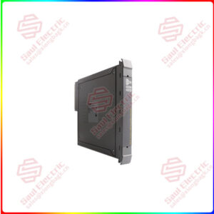
IS200EPDMG1B  EXCITER POWER DISTRIBUTION MODULE

Part No.: IS200EPDMG1B
Manufacturer: General Electric
Country of Manufacture: United States(USA)
Product Type: Power Distribution Board
Series: EX2100

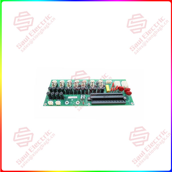
IS200EPDMG1B is an Exciter Power Distribution Module developed by GE under EX2100. It is employed in the EX2100 Excitation Control to supply power to the exciter’s control, I/O, and protection boards. It is located on the side of the Exciter Power Backplane (EPBP) and is powered by one or two 120 V ac inputs in addition to the station battery’s 125 V dc output. A board-mounted terminal block (TB1) serves as the entry point for all power supply inputs and filters them.

Categories: ,

Description

Overview


Essential details:IS200EPDMG1B  EXCITER POWER DISTRIBUTION MODULE

Part No.: IS200EPDMG1B
Manufacturer: General Electric
Country of Manufacture: United States(USA)
Product Type: Power Distribution Board
Series: EX2100

IS200EPDMG1B is an Exciter Power Distribution Module developed by GE under EX2100. It is employed in the EX2100 Excitation Control to supply power to the exciter’s control, I/O, and protection boards. It is located on the side of the Exciter Power Backplane (EPBP) and is powered by one or two 120 V ac inputs in addition to the station battery’s 125 V dc output. A board-mounted terminal block (TB1) serves as the entry point for all power supply inputs and filters them. In an external AC to DC converter, each ac supply is rectified to 125 V dc (DACA). The resulting two or three dc voltages are connected together using external diodes to provide the P125V and R125V dc source power supplies. These voltages are nominally +62.5 V and -62.5 V to the ground and are center grounded.

IS200EPDMG1B Features

  • Through four of the holes on the board for mounting, the module is safety grounded and chassis ground. The external DACA#1 and DACA#2 are connected to the terminal block’s AC1 and AC2 by two 12-plug connections (JDACA1 and JDACA2), and the DACA outputs are then connected to the 125 V dc lines (P125 and R125).
  • With the exception of the EXTB board, each individual power supply output to an exciter board is fused, equipped with an on/off toggle switch, and has a green LED indicator to indicate power availability.
  • Three Exciter Gate Pulse Amplifier Boards (EGPA), Exciter Terminal Board (EXTB), and three Exciter Power Supply Modules (EPSM) feeding three controllers are all capable of receiving power from the outputs. Each output has its own connector, which is attached to the EPBP for distribution.

Application Data

  • A 24-point terminal block, ten plug connectors, seven switches, fourteen fuses, four grounded mounting holes, eight LED indicators, and a single adjustable jumper are all parts of the EPDM module. Each connector has a 600 V ac or dc rating.
  • All switches are rated at 125 V dc, 6 A, but the terminal board is rated at 300 V (10 A per pin). On systems with external reference, the adjustable jumper (BJS) isolates the ground reference.

Handling Precautions

  • Use static-sensitive handling techniques on all boards to avoid component damage due to static electricity.
  • When handling boards or components, use a wrist-grounding strap, but only after the boards or components have been taken out of potentially electrified machinery and are at a normally grounded workstation.

IS200EPDMG1B

lf you need to inquire or purchase ,please send the product models to my email or call medirectly .

sunny  He

[Email] sales@xiongbagk.cn

[Mobile] 86-18059884797

[WhatsApp] 86-18059884797

[Skype] sales@saulcontrol.com

IS200EPDMG1B  EXCITER POWER DISTRIBUTION MODULE

IS200EPDMG1B Replacement Procedures

  1. Check if the exciter has been de-energized.
  2. Check that the power is off before touching any electrical circuits by opening the control cabinet door and using high voltage testing equipment.
  3. Take note of every switch’s location on the board, then turn them all off.
  4. Carefully detach every cable connector from the board and remove it from the EPDM module. To make reconnection easier, ensure all wires are identified with the correct connector name (as indicated on the board).