Description
Overview
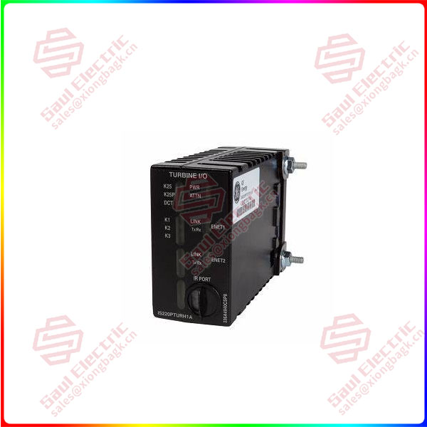
Essential details:IS220PPDAH1A POWER DISTRIBUTION SYSTEM FEEDBACK
lf you need to inquire or purchase ,please send the product models to my email or call medirectly .
sunny He
[Email] sales@saulcontrol.com
[Mobile] 86-18059884797
[WhatsApp] 86-18059884797
[Skype] sales@saulcontrol.com
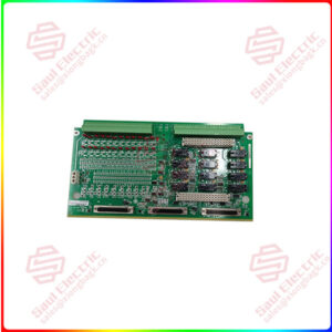
IS220PPDAH1A POWER DISTRIBUTION SYSTEM FEEDBACK
Part Number: IS220PPDAH1A
Manufacturer: General Electric
Series: Mark VIe
Product Type: I/O Pack
Availability: In Stock
Country/Region of Manufacture: United States
Manual: GEH-6721_Vol_II V
FUNCTIONAL DESCRIPTION
IS220PPDAH1A is a Power Distribution System Feedback Board manufactured and designed by General Electric as part of the Mark VIe Series used in distributed control systems. The Power Distribution System Feedback (PPDA) I/O pack can receive inputs from as many as six power distribution boards or as many as six sets of feedback signals. It offers the controllers a second redundant Ethernet interface while adjusting the board feedback signals. In order to identify the power distribution boards hooked into the PPDA feedback, electronic IDs are used in a plug-and-play design. By populating the IONet output with this data, connected boards can subsequently receive accurate feedback.
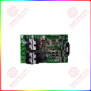
The Mark VIe Control Power Distribution Module’s JPDS, JPDM, JPDG, or JPDC 28 V de control power distribution board serves as the host for the PPDA I/O pack (PDM). 50-pin ribbon cable jumpers wired pin to pin 1 are used to connect other boards. The PPDA receives one feedback group from each board.
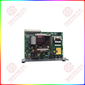
The PPDA I/O pack includes one of the following compatible BPPx processor boards:
- There is a BPPB processor board inside the PPDAHIA.
- The ControlST software package V04.07 and later is compatible with the functionally compatible BPPC processor board found within the PPPDAHIB.
- The JPDB, JPDE, and JPDF feedback signals are compatible with the PPDA I/O pack.
INSTALLATION:
- Mount the selected terminal board firmly.
- Directly connect the JAI terminal board connectors to the PPDA I/O pack. The JPDG, JPDS, JPDM, or JPDC 28 V de control power distribution board is where the PPDA I/O pack is mounted.
- Using the threaded screws next to the Ethernet ports, mechanically secure the I/O pack. The studs slip into a mounting bracket made for the particular style of the terminal board. It is important to position the bracket such that the DC-62 pin connector connecting the I/O pack and the terminal board is not subjected to right-angle forces. In the course of the product’s service life, the adjustment should only be necessary once.
- Depending on how the system is set up, connect one or two Ethernet wires. Either port can be used to use the I/O pack. If twin connections are employed, it is customary to link ENETI to the network related to the R controller.
- Connect the pack’s connector to a power source to turn on the battery. The I/O pack includes a built-in soft-start feature that limits current inrush when power is applied, so it is not essential to unplug the cable before connecting it.
- If necessary, set up the I/O pack using the ToolboxST program. Consult the section
- Ribbon cables should be connected from connection P2 on JPDG, JPDS, JPDM, or JPDC to additional core boards supplying data to PPDA.
SIGNAL ROUTING:
The JPDG, JPDS, JPDM, or JPDC board is where the PPDA I/O pack is mounted. 50-pin ribbon cable jumpers wired pin to pin 1 are used to connect other boards. One feedback group is contributed to PPDA by each board. There are up to five prior boards that this connection goes through. This connection can be seen in the following figure.


 1 Year Warranty
