Description
Overview
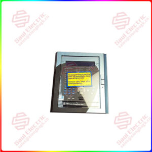
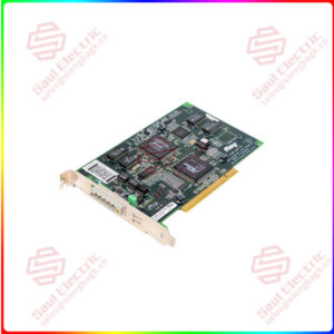
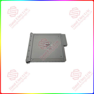
Essential details:IS230TCISH6C DIN RAIL I/O MODULE
Part Number: IS230TCISH6C
Manufacturer: General Electric
Series: Mark VIe
Function: DIN Rail I/O Module
Mounting Option: DIN Rail Mounting
Input filter: Hardware filter, 4 ms
Number of relay: 12
Technology: Surface-mount
Temperature: -30 to + 65 degrees Celsius
Product Type: PCB
Availability: In Stock
Country of Manufacture: United States (USA)
Functional Description
IS230TCISH6C is a DIN Rail I/O Module manufactured and designed by General Electric. It is a part of the Mark VIe Series used in GE Distributed Control Systems. The Mark VIe I/O modules are used in turbine and plant control systems. Its I/O modules reflect this diversity, with a wide variety of types and the ability to distribute them either individually or in clusters. I/O modules are made up of an I/O pack that is mounted on a terminal board. The I/O pack includes a local processor running the QNX operating system as well as a data acquisition board. The terminal board includes a field wiring terminal block and passive circuits that connect the terminal block to the I/O pack. In the unlikely event that the module’s passive circuits fail, terminal blocks can be removed with field wiring attached.
Features
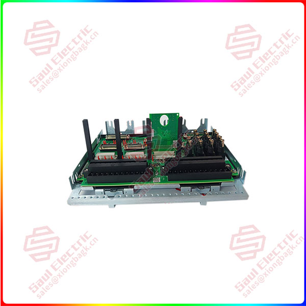
- Terminal Blocks: Consists of two terminal blocks, each featuring two rows of screw connections. These terminal blocks provide a convenient and secure method for connecting wires and cables to the I/O module. The blocks are mounted in a single line on one long side of the card and are held together by two screws, ensuring stability and reliability in the connections.
- Connectors: On the other side of the board, there are three 37-pin female connectors. These connectors serve as the interface for connecting external devices or other components to the I/O module. They allow for seamless transmission of signals and data between the module and the connected devices.
- Plug Connectors: Features two plug connectors, providing additional connectivity options. These connectors can be used to interface with other compatible modules or equipment, expanding the versatility and integration capabilities of the I/O system.
- Metal Carrier and DIN-Rail Compatibility: Housed in a metal carrier, which provides physical protection and support for the module. The metal carrier is designed to be DIN-rail compatible, allowing for easy and secure mounting onto standard DIN rails commonly found in industrial environments. This ensures proper installation and integration of the module into the overall system setup.
- Chassis Grounding: Equipped with factory-made holes that serve as chassis grounding screws. These grounding screws are specifically intended for SCOM (grounding) purposes and should have the shortest possible connection. Proper grounding is crucial for electrical safety and to mitigate any potential electrical interference or disturbances that may affect the performance of the I/O module and the connected devices.
IS230TVBAH2A
lf you need to inquire or purchase ,please send the product models to my email or call medirectly .
sunny He
[Email] sales@xiongbagk.cn
[Mobile] 86-18059884797
[WhatsApp] 86-18059884797
[Skype] sales@saulcontrol.com
IS230TCISH6C DIN RAIL I/O MODULE
I/O Module Characteristics
- I/O modules are made up of an I/O pack that is mounted on a terminal board. The I/O pack includes a local processor running the QNX operating system as well as a data acquisition board. The terminal board includes a field wiring terminal block and passive circuits that connect the terminal block to the I/O pack.
- In the unlikely event that the module’s passive circuits fail, terminal blocks can be removed with field wiring attached. contain two barrier type, pluggable terminal blocks with 24 points each. With ring type lugs, each point can accept two 2.05 mm2 (0.081 in2) #12 AWG wires with 300 V insulation. Captive clamps are also provided for terminating bare wires.
- Center-to-center screw spacing is 9.53 mm (0.375 in). T-type modules are typically base-mounted and can accommodate multiple I/O packs. Box type terminal blocks on S-type modules accept one 2.05 mm2 (0.081 in2) #12 AWG wire or two 1.63 mm2 (0.064 in2) #14 AWG wires with 300 V insulation per point. Center-to-center screw spacing is 5.08 mm (0.2 in). S-type modules are DIN-rail and base mounted, with a single I/O pack.
Installation
- Mounting on a Sheet Metal Carrier: The component, along with the plastic insulator, is mounted on a sheet metal carrier. The carrier provides structural support and protection for the component. The component and insulator are securely attached to the carrier to ensure stability during operation.
- Mounting on a DIN Rail: The sheet metal carrier, with the component and insulator mounted on it, is then mounted on a DIN rail. DIN rails are commonly used in industrial environments as a standardized method for mounting control and automation components. The DIN rail ensures secure and standardized installation of the component.
- Mounting in a Cabinet: In some cases, the board plus insulator assembly can be mounted on a sheet metal assembly, which is then bolted into a cabinet. This method allows for more organized and compact installation within the cabinet, facilitating easy access and maintenance of the component.
- Wiring Connections: The connections to the component are typically made by wiring directly to two sets of 48 terminal blocks. 18 AWG wires are commonly used for these connections. The upper set of terminals, known as TB1, is connected to the relay portion of the board, while the lower set of terminals, TB2, is connected to the contact input circuits. These terminal blocks provide a secure and reliable connection for the necessary wiring.
- Screw Assignments and Shield Termination: The screw assignments for the two sets of terminal blocks (TB1 and TB2) are the same as those on the relay board and the contact input terminal board. This standardization ensures consistency and ease of installation. Additionally, when using shielded cables, the shields should be properly terminated with their own bracket or grounding point to maintain proper grounding and minimize electromagnetic interference.


 1 Year Warranty
