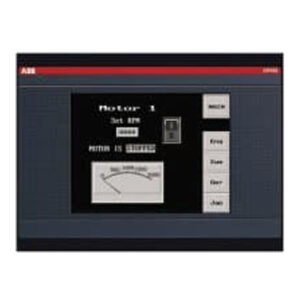
Description
Overview
Essential details:PP885 3BSE069276R1 Panel 800 Version 6 – PP885
• The operator panel is designed for stationary installation on a planar surface, where the following conditions are fulfilled:
– no high explosive risks
– no strong magnetic fields
– no direct sunlight
– no large, sudden temperature changes
• Install the operator panel according to the accompanying installation instructions.
• Ground the operator panel according to the accompanying installation instructions.
• Only qualified personnel may install the operator panel.
• Separate the high voltage, signal and supply cables.
• Make sure that the voltage and polarity of the power source is correct before connecting the operator panel to the power outlet.
• Peripheral equipment must be appropriate for the application and location.
• In a Zone 2 environment, this equipment shall be installed in an enclosure that provides a degree of protection not less than IP 54 or greater than IP 65 in accordance with IEC/EN 600079-0. The IP rating of the equipment is limited to the IP rating of the enclosure it is to be installed into.
• In a Zone 22 environment, this equipment shall be installed in an enclosure that provides a degree of protection not less than IP 64 or greater than IP 65 in accordance with IEC/EN 600079-0. The IP rating of the equipment is limited to the IP rating of the enclosure it is to be installed into
Connect the cables in the specified order, according to the drawing and steps below.
• The operator panel must be brought to ambient temperature before it is started up. If condensation forms, ensure that the operator panel is dry before connecting it to the power outlet.
• Ensure that the operator panel and the controller system have the same electrical grounding (reference voltage level), otherwise errors in communication may occur.
• Ensure that the voltage and polarity of the power source is correct.
• Separate high voltage cables from signal and supply cables.
• Shielded communication cables are recommended.
– Connect cable A.
– Connect cable B, using an M5 screw and a grounding conductor (as short as possible), that is sized correctly according to local electrical codes.
– Connect cable C.
– Connect cable D. The recommended cross-section of the cable is 1.5 mm2..
6. Carefully remove the protective film over the operator panel display, take care to avoid static electricity that could damage the panel.
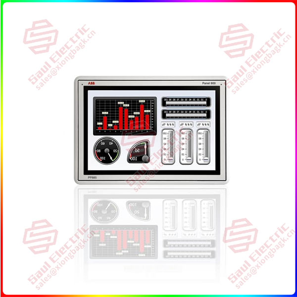
PP885 3BSE069276R1
lf you need to inquire or purchase ,please send the product models to my email or call medirectly .
sunny He
[Email] sales@xiongbagk.cn
[Mobile] 86-18059884797
[WhatsApp] 86-18059884797
[Skype] sales@saulcontrol.com
PP885 3BSE069276R1 Panel 800 Version 6 – PP885


 1 Year Warranty
