Description
Overview
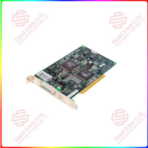
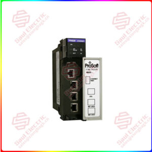
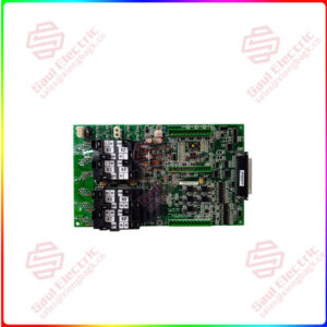
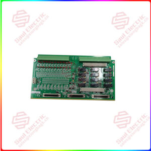
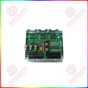
Essential details:T8310C TrustedTM TMR Expander Interface
DESCRIPTION
The TrustedTM TMR Expander Interface module resides in the TrustedTM Controller Chassis and provides the ‘master’ interface between the Inter-Module Bus (IMB) in the Controller Chassis and the Expander Bus. The Expander Bus allows multiple chassis systems to be implemented using UTP cable connections whilst maintaining the fault tolerant, high bandwidth IMB capabilities.
The module provides fault containment for the Expander Bus, the module itself and the IMB in the Controller Chassis, ensuring that the effects of these potential faults are localised and system availability maximised. The module is fault tolerant with HIFT TMR architecture. Comprehensive diagnostics, monitoring and testing provide rapid fault identification. Hot standby and module spare slot configurations are supported, allowing automatic and manual repair strategies.
The TMR Expander Interface is a fault tolerant design based on TMR architecture arranged in a lockstep configuration. Figure 1 shows, in simplified terms, the basic structure of the TMR Expander Interface.
The module has three main fault containment regions (FCR A, B and C). Each of the main FCRs contains interfaces to the Expander Bus and Inter-Module Bus (IMB), an active/standby interface to the other TMR Expander Interface in the chassis, control logic, communications transceivers and power supplies.
Communication between the module and the TMR Processor is via the IMB on the backplane of the Controller Chassis. The IMB provides fault tolerance and high bandwidth communications between the Interface Modules and the TMR Processor. All transactions are voted, localising faults to the IMB should they occur.
Communication between the Interface Module and the TMR Expander Processor in the Expander Chassis is via the Expander Bus. The Expander Bus is triplicated, point-to-point architecture. Each channel of the Expander Bus comprises separate command and response media. Voting is provided at the Expander Bus Interface to ensure that cable faults are tolerated, and the remainder of the Expander Processor operates in a fully triplicated mode, even in case of cable faults occurring. A fourth FCR (FCR D) provides the non-critical monitoring and display functions and is also part of the inter-FCR Byzantine voting structure. Isolation is provided between FCRs wherever interfaces are required, to ensure that faults can not propagate between them.
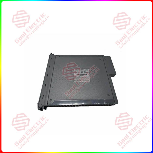
T8310
Product parameter
• Hardware Implemented Fault Tolerant (HIFT) architecture
• Dedicated hardware and software test regimes which provide very fast fault recognition and response times
• Automatic fault handling without nuisance alarming
• Hot replacement
• Front panel indicators that show module health and status.
• T2V Certified IEC 61508 SIL 3
APPLICATION
The Expander Interface Modules may reside in any of the I/O slots within the Controller Chassis. The modules are installed in pairs with the left-hand module occupying an odd numbered slot. The
Expander Interface must NOT be installed in these other module locations, as this may cause damage to the module.
The two Interface slots must be interconnected using the Expander Interface Adaptor Unit T8312.
The Expander Interface Modules are connected to the Expander Processor Modules by the Expander Interface Hot Link Cable TC-301 via the TrustedTM Expander Interface Adaptor Unit T8312.
The connection to remote Expander Chassis is via the TrustedTM Fibre Optic Tx/Rx Unit using the Expander Interface Adaptor to Fibre Tx/Rx Unit (Remote Expanders) Cable TC-302.
THE MODULE CONTAINS STATIC SENSITIVE PARTS. STATIC HANDLING PRECAUTIONS MUST BE OBSERVED. SPECIFICALLY ENSURE THAT EXPOSED CONNECTOR PINS ARE NOT
TOUCHED. UNDER NO CIRCUMSTANCES SHOULD THE MODULE HOUSING BE REMOVED.
Before installation, visually inspect the module for damage. Ensure that the module housing appears undamaged and inspect the I/O connector at the back of the module for bent pins. If the module appears damaged or any pins are bent, do not install the module. Do not try to straighten bent pins.
Return the module for replacement.
Ensure that the module is of the correct type.
Record the module type, revision and serial number of the module before installation.
If the module is to reside in a new chassis, or the system is being configured for the first time, ensure that the chassis address has been set correctly before installing the modules. See Controller Chassis Product Description (PD-8100) for further details.
To install the module:
1. Ensure that the cable assembly is correctly located.
2. Release the ejector tabs on the module using the release key. Ensure that the ejector tabs are fully open.
3. Holding the ejectors, carefully insert the module into the intended slot.
4. Push the module fully home but pressing on the top and bottom of the module fascia.
5. Close the module ejectors, ensuring that they click into their locked position.
lf you need to inquire or purchase ,please send the product models to my email or call medirectly .
Same day shipment of 1000 parts
My company under the Sales and Marketing Department, technical engineering Department, after-sales service department, the department of comprehensive management. We can help your business with good service.
1. Sales Department 24/7 service. Handles your requests for any PLC DCS products in a timely manner with patience and professionalism.
2. The engineering department ensures that the products have no quality problems. All products will be inspected before shipping.
3. The financial department checks the payment and refund in time.
4. The warehouse department will carefully check the list of goods, carefully pack them, and deliver the goods in time.
5. After-sales Service Department has a full-time after-sales service team, subordinate to the sales department, and users can timely respond to service requests.

Shipping
Superiority products T8310C TrustedTM TMR Expander Interface
| ABB PM865K01 3BSE031151R1 | BANNER LS4ELQ | METSO D100644 |
| GE SR469-P5-HI-A20-E | Schneider Electric XBKH70000002M | YOKOGAWA PW301 |
| GE SR469-P5-HI-A20 | Agilent HP-5517B | ABB GFD233A 3BHE022294R0103 |
| GE SR469-P5-HI-A20-E | PROSOFT PTQ-PDPMV1 | ABB GFD233A103 3BHE022294R0103 |
| ABB S-076N 3BHB009884R0021 | ABB PCD232A 3BHE022293R0101 | BASLER A404K |
| ABB 5SDF1045H0002 | ABB PPD113B03-26-100100 3BHE023584R2625 | NOVOTRON ND32-5610 ND32-5610VS-101-011-31 |
| ABB 3BHL000986P0006 | ABB REF542PLUS 1VCF752000 | A-B 2098-DSD-030-SE/B |
| ABB 5SHY3545L0010 3BHB013088R0001 3BHE009681R0101 GVC750BE101 | ABB REF542PLUS 1VCR007346 | Bentley 330101-00-08-20-12-05 |
| ABB 5SHY4045L0006 3BHB030310R0001 3BHE039203R0101 GVC736CE101 | PROSOFT PTQ-PDPMV1 | AB 2094-BM01-S/C |
| ABB 5SHY4045L0001 3BHB018162R0001 3BHE009681R0101 GVC750BE101 | ABB PFEA113-65 3BSE050092R65 | METSO ACN CS |
| EATON MP3010 | Honeywell CC-IP0101 51410056-175 | ABB PPC907BE 3BHE024577R0101 |
| TRICONEX 2101 | RELIANCE 61C22A | ABB REF615A_1G HAFNAEFCBGC1BQK11G |


 1 Year Warranty
