Description
Overview
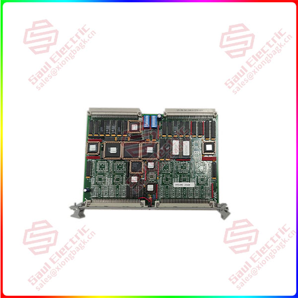
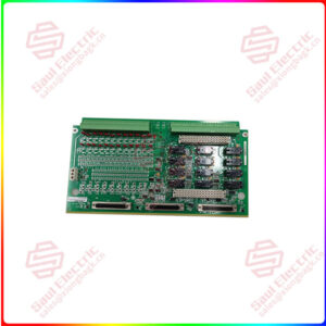
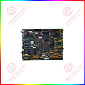
Essential details:VMIVME-2540-000 Industrial controller motherboard
lf you need to inquire or purchase ,please send the product models to my email or call medirectly .
sunny He
[Email] sales@saulcontrol.com
[Mobile] 86-18059884797
[WhatsApp] 86-18059884797
[Skype] sales@saulcontrol.com
VMIVME-2540-000 Industrial controller motherboard
The ICC counter circuitry consists of six programmable System Timing Controllers (STCs). Each STC provides the ICC with four high-speed counter/waveform synthesis interfaces, giving the VMIVME-2540 twenty-four channels of digital measurement and control. The STC counters may be configured individually or in groups of up to four to implement the various measurement and control functions.
The on-board 68HC000 CPU configures and manages each STC interface directly, allowing the VMEbus host interface to be elevated above the hardware level. Ordering options allow the VMIVME-2540 to be factory configured with 1, 2, 4, or 6 System Timing Controllers. The inputs and outputs of the System Timing Controllers are buffered at the front panel connectors with RS-422 line receivers and line drivers. TTL input signal compatibility is supported by connecting the inverting input of the RS-422 line receiver to an on-board 1.4 V reference through the front panel, and the TTL signal to the noninverting input.
The user interface of the Intelligent Counter/Controller is implemented by a 15 MHz 68HC000 CPU supported by 64 Kbyte of EPROM firmware, 128 Kbyte of zero-wait-state static RAM, and highly-integrated control and interrupt logic. The VMEbus host programs the ICC by queueing function control blocks in local memory and issuing commands. The CPU responds to the commands by interpreting the function control blocks, configuring the system timing controllers, and then acknowledging the host command. Once configured, the CPU maintains data structures of measurement data in local memory and interrupts the VMEbus host when a measurement or control process is complete.


 1 Year Warranty
