Description
Overview
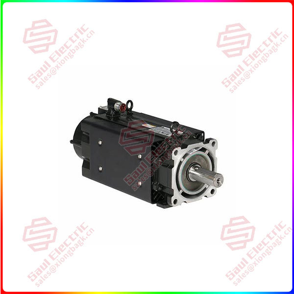
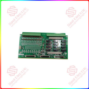
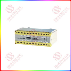
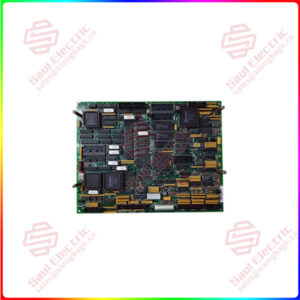
Essential details:VPS-B1653D-PJ12DF Kinetix VP Series Washdown Servo Motor
lf you need to inquire or purchase ,please send the product models to my email or call medirectly .
sunny He
[Email] sales@xiongbagk.cn
[Mobile] 86-18059884797
[WhatsApp] 86-18059884797
[Skype] sales@saulcontrol.com
VPS-B1653D-PJ12DF Kinetix VP Series Washdown Servo Motor
To remove a shaft key, perform one of these actions:
• Grasp the key with a plier or similar tool, and lift the key out of the key slot.
• Insert a screwdriver between the key and the bottom of the key slot, and use a levering action to lift the key out of the key slot.
To install a shaft key, follow these steps.
1. Verify that the replacement key matches the keyway in the shaft and the mating mechanical connection, for example, a coupling or pulley, before proceeding.
2. Align the front of the key with the front of the motor shaft.
This prevents the curved end-of-cut at the motor end of the keyway from interfering with the correct seating of the key.
3. Support the underside of the shaft diameter with a fixture, and use a controlled press device to apply a constant force across the top surface to press the key into the shaft.
The shaft seal can be safely removed by partially inserting an appropriately sized screw or bolt into the face of the shaft seal. The head of the screw or bolt provides a convenient point to grasp and remove the shaft seal.
Before installing the screw, create a pilot hole appropriate for the screw being used. Use masking tape or a depth sleeve to establish a drilling depth limit of 4 mm (0.16 in.) from the tip of the drill bit.
1. Install a threaded rod and nut in the shaft alignment hole.
The table below lists the diameter and threading of alignment holes, and a recommended rod length for each motor.
2. Tighten the nut on the threaded rod against the end of the motor shaft.
This prevents the threaded rod from backing out of the motor shaft during this removal/installation procedure.
3. Position the slinger squarely on the end of the motor shaft.
4. Place a deep well socket, a larger washer, and a nut on the threaded rod.
Use a socket larger than the shaft diameter to provide sufficient clearance between the inside surface of the socket and the motor shaft. The table below lists shaft diameters for various motor sizes.


 1 Year Warranty
