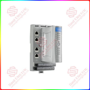
Description
Overview
Essential details:WT3004E Precision Power Analyzer
By using the motor evaluation function (option), the rotating speed, torque, and output of a motor can be determined from the signal that is proportional to the rotating speed of the motor, and the signal received from a torque meter, which is proportional to the motor’s torque. The signal applied from the revolution sensor or torque meter to this instrument can be selected from analog signal (DC voltage) or pulse signal. In addition, the synchronous speed and slip of a motor can be determined by setting the motor’s number of poles. Furthermore, the active power and frequency that are measured by this instrument and the motor output can be used to compute the motor efficiency and the total efficiency.
• Line Filter and Measurement Mode
• The line filter setting is common to all measurement modes except cycle-by-cycle measurement mode. The initial setting is OFF.
• The line filter setting in cycle-by-cycle measurement mode is independent of the setting in other measurement modes. The initial setting is 50 kHz.
• Selecting the Synchronization Source
• Select which element’s input signal will be used as a synchronization source (synchronized to the zero-crossing point of the selected signal) when measuring the analog signal of the revolution signal and torque signal. Select the signal to be the synchronization source from the choices below. The selectable items vary depending on the installed elements. U1, I1, U2, I2, U3, I3, U4, I4, Ext Clk (external clock)* , and None * For the specifications of the Ext Clk (external clock), see the explanation in section 7.4.
• The measurement period determined by the synchronization source selected here is used to measure the analog signal of the revolution signal and torque signal. If you specify no synchronization source by selecting “None,” the entire sampled data within the data update interval is the data used to determine the rotating speed and torque. For details on the synchronization source, see appendix 6 in the User’s Manual IM WT3001E-01EN.
• If the rotating or torque signal is a pulse signal, the average of the pulse signal interval over the measurement period determined by the synchronization source selected here is the measured value of the rotating or torque signal. If the pulse signal interval is not within this measurement period, the measured value is determined from the previous interval.
• To achieve stable measured values by matching the measurement period with the measurement functions of voltage, current, active power, and so on such as during the measurement of the motor efficiency, it is recommended that the synchronization source be set to the same synchronization source specified in section 4.7 in the User’s Manual IM WT3001E-01EN.

WT3004E
lf you need to inquire or purchase ,please send the product models to my email or call medirectly .
sunny He
[Email] sales@xiongbagk.cn
[Mobile] 86-18059884797
[WhatsApp] 86-18059884797
[Skype] sales@saulcontrol.com
WT3004E Precision Power Analyzer
The selectable range of pulse range of input signals is as follows:
• Revolution signal: 0.0001 to 99999.9999 [rpm]
• Torque signal: –10000.0000 to 10000.0000 [N·m] If the input signal type is Pulse, the upper and lower limits of the waveform display are set to the values specified here.
• On models with the D/A output (option), the rated value of the D/A output is as follows.


 1 Year Warranty


